Among the subjects taught in my discipline is the basic crystallography of aluminosilicates, particularly clay minerals, but including other primary minerals that are major constituents of soil. My research involves molecular templating of crystals, and so relies upon inference of a exact level of correspondance between structural units.
As delivered, the Polyhedral Model Kit (PMK) available from the Institute for Chemical Education consists of:
My difficulty starts with the connectors supplied, since the 2-prong connectors do not match the bond angles of apex-to-apex silica tetrahedra and the 4-prong connectors do not match in bond number or bond angle the edge-to-edge alumina octahedra that bond to apical silica tetrahedra. (The bond number problem can be solved by trimming a connector off the 4-prong connector, but the bond angle problem remains.)
The connectors are flexible and can bend to make the necessary bonds but to the learner it does not seem that the fit of the structural units is as precise as they are indeed in nature.
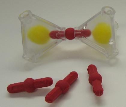
Consider the straight, 2-prong connector and the apex-to-apex tetrahedra. As seen in the adjacent figure (left), at rest the connectors to the tetrahedra do not permit a plane of basal silica. Using a connector with the correct bond angle, the tetrahedra arrange themselves in the 'anatomically correct' pose with a basal plane (right).
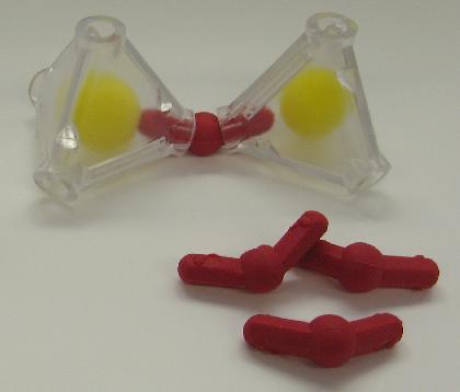
The existing 4-prong connectors bond two octahedra edge-to-edge convincingly using the 90-degree separation, but the third connection to a tetrahedral layer is confusing to the novice because of the improper bond angles, even if the connector is pruned to 3-connectors only. However, when a 3-prong connector is supplied with correct angles (see left), the construction is quite straightforward, the product is pleasingly clear, and the next set of structural units and their orientation is suggested by the connectors.
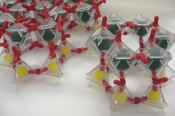
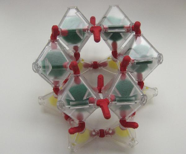
The difference apparent in the 'cleanness' of an assembled model with correct bond angles (right) can be seen in the adjacent photo of kaolinite assembled with connectors as originally supplied (left).
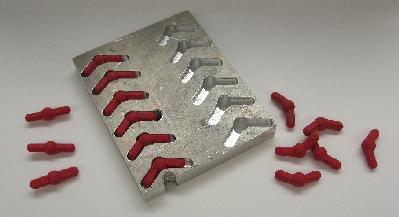
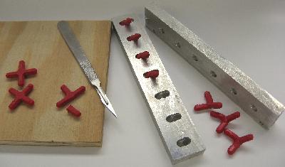
For the limited purposes of these trials, the connectors supplied were remanufactured in-house by reheating using appropriately designed forms.
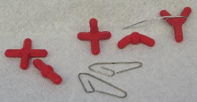
A low-tech alternative is to 'bind' the connectors in the proper
configuration using paperclips, which can produce bent 2-prong,
3-prong, and 4-prong connectors (the latter shaped to approximate an sp3
orbital and create a tetrahedral orientation of polyhedra around the
connector itself.)
[Technical notes: The 2-prong connectors were modified to have a 120° angle, and the 3-prong connector to have a 100° angle between two arms, with the third inclined 30° above the plane of the first two. Heating the connectors in the forms for 30-60 minutes, followed by quenching in cool water, was sufficient to make these angles permanent.]